


Summary
- Metrological verification of air particle counters: constructing a test bench to measure counting efficiency according to ISO 21501-4.
- On the importance of monitoring the parameters of the treated water supply used in the manufacture of water for pharmaceutical use on production premises.
- New technologies for single-use biopharmaceutical process flow measurement
- The Calibration of Embedded Sensors
- Cleaning and disinfection - A one or a two steps process or scientifically justified ?
- Updated regulations on FDA acceptance of medical device clinical data in effect soon.
Using onboard sensors has been democratized in recent years but the calibration of these sensors is a problem that is not framed by especially standards for thermal validation use. Their wide operating range allows use in extreme environments:

- Steam sterilizers (high temperature and pressure).
- The environmental chambers (low temperature and atmospheric pressure).
- Ovens / tunnels pyrogenic (high temperature)
- Sterilization in place (SIP / SIP)
- Process of cooking.
- Cryo preservation Freeze Dryers
Their size, ease of use, time saving to the implementation probes give embedded unmatched flexibility to meet the temperature monitoring applications in all industries.
Particularly used in the food industry in its infancy, they are becoming essential for over 15 years in the pharmaceutical and biotech.
1. A little history…
To qualify production equipment solutions that were available to us were few. The use of central wireline acquisition was widespread. This technology offered and still offers advantages in terms of range of use, interchangeability of sensitive measuring elements (thermocouples) and reliability over the long term. But the implementation is difficult. The standards for they brought their share recommendations with calibration and adjustment prior study (commonly known as Pre-Qual) and calibration performed after the acquisition (Post -Qual). This provides a framework metrologically probe state before and after the test and determine the metrological status of the measuring chain and to determine compliance of the equipment under test.
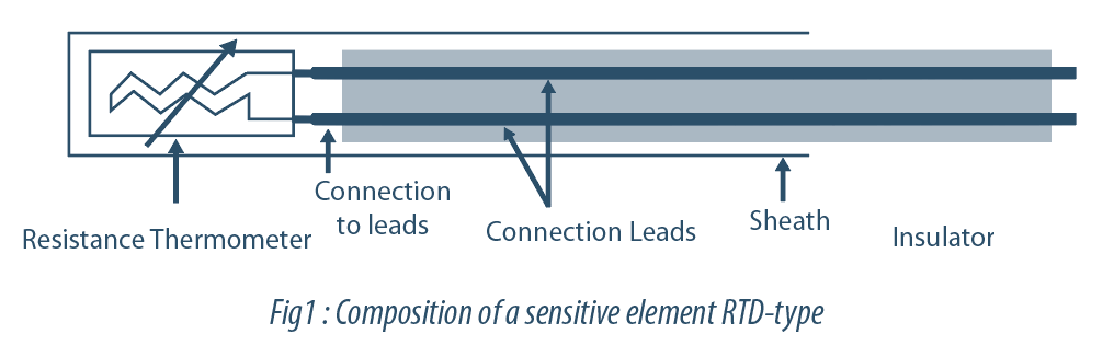
Industry employs the use of sensitive elements type RTD (Resistance Temperature Detectors) or PRT (Platinum Resistance Thermometer), better known by the abbreviations PT-100, PT-1000, for stationary applications, system regulation, monitoring online process. Such sensitive measuring elements is reputedly more accurate and less drift compared with thermocouple.
But what about when the RTD becomes embedded …
2. La technologie RTD (PT-100, PT-1000)
RTDs operate on the principle of electrical resistance variations pure metals and are characterized by a positive linear change in resistance depending on the temperature. Specifically, when heated, the resistance of the metal increases, and vice versa once cooled, it decreases. Typical elements used for RTDs include nickel (Ni) and copper (Cu), but platinum (Pt) is by far the most common, due to the extent of its range of temperatures, its precision and its stability.
Passing the current through an RTD generates a voltage across the RTD. By measuring this voltage, you can determine its resistance and, thus, its temperature. Also, because they require current excitation, they are subject to a temperature rise (self-heating).
Popular for their stability, RTDs exhibit the most linear signal of all electronic sensors for temperature. However, they generally cost more than their counterparts because of their more delicate construction and use of platinum. RTDs are also characterized by a slow response time, low sensitivity and vulnerability to physical shock and moisture. x chocs physiques et à l’humidité.
widespread practices for the metrological monitoring of embedded sensors
With the development of this technology, it was highlighted different approaches to monitoring metrology probes:
Method 1: The most common approach: the user does not make any metrological control probes during the year and return probes for annual calibration in an accredited calibration laboratory or not.
Méthod 2: Growing approach, the user performs calibration of probes internally or via a lab at higher frequencies (four times a year, for example) – according to its level of use
Méthod 3:. Historical approach: the user performs a calibration before and after each study / measurement campaign. Method used originally with wired technology (thermocouples).
Each method has its advantages and disadvantages. To determine the appropriate method for your use, different criteria come into play:
- Criticality of the application.
- MPE (maximum permissible error) applicable to applications.
- Metrological traceability.
- Frequency of use.
- metrological resources available internally.
- Number of users and turnover.
- Cost.
To choose the right one must ask the right questions to determine with a risk analysis the impact that could have an onboard sensor improper metrologically.
For example using method 1 (annual metrological verification only) Below a risk assessment table on a concrete application (steam sterilizer) – simplified approach:
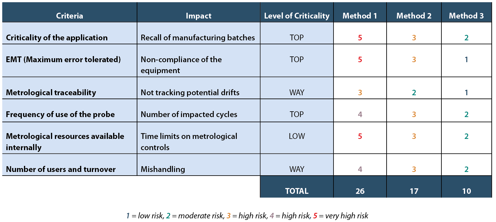
Not surprisingly it is clearly shown in this example, the method 1 (score: 26) has multiple high risk factors.
Example: an embedded probe sent calibration and showing significant drift ± 0.5 ° C, below the impact on criticality as well as the MPE:
Application criticality = questioning of all measurements with this probe on each study / qualification of equipment. A drift + 0.5 ° C can make improper many of your cycles. The difficulty is to assess when the sensor to drift, and in the absence of metrological testing throughout the year is questioning throughout the past year. This can have impact as a reminder of post production batches.
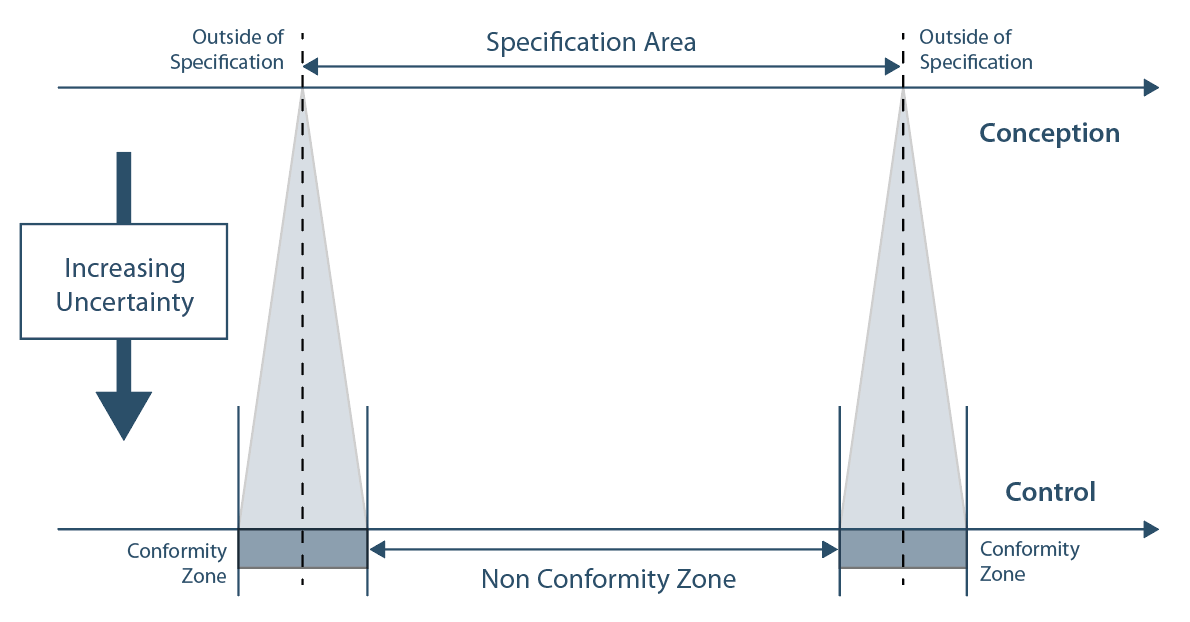
EMT = as EMT for a sterilizer according to the procedures is around +/- 1 ° C, the result is that the drift does not maintain a factor of 3 between the equipment of the EMT and the uncertainty of the probe. same impact on the criticality of the application. As shown in the illustration below, the greater your probes derived more compliance area is reduced and the risk of non-compliance is more important.
The use of embedded probes requires some precautions because of their sensitivity to mechanical shocks, humidity and to a lesser extent to thermal shocks. It is important to have a level of training promulgated by the supplier to reduce the risks associated with operator manipulation.
3.1 Calibration method for embedded probes
Méthod 1
As part of an annual metrological monitoring from an accredited laboratory or not, you should check that the methods and calibration means are aligned with your hardware. It will mainly check:
- The level of uncertainty of the calibration laboratory is in line with the level of uncertainty of your sensors with a minimum factor x3. Call an ISO 17025 accredited laboratory allows for validated methods and audited by competent bodies.
- Their calibration procedure is in accordance with manufacturer recommendations.
- Focus calibration with adjustment to avoid to calculate for yourself the impact of derivatives on the year ahead.
Méthod 2
Through more frequent metrological monitoring by an external laboratory, it is always necessary to apply the same recommendations given in Method 1.
It is now possible to perform in-house. Current technology allows you to calibrate your sensors with an adequate level of uncertainty website (as long as you select its calibration means). This calls for:
- To define an appropriate calibration frequency. It must match the on-site equipment use intensity.
- The gap analysis between calibrations will subsequently decide to maintain or space that frequency.
Exemple.
new to embedded sensors, will perform calibrations after 3 consecutive trials, and gradually space out the interval to create a history and perform a risk analysis on the calibration interval. This approach will have elements as part of internal or external audit to justify your metrological approach.
Méthod 3
Differs mainly from method 2 with the most important and constant frequency of your calibrations.
4. Calibration Means
4.1 The temperature generator
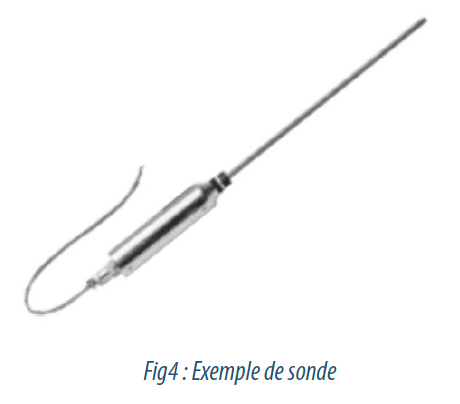
The “embedded” probe to its name, it is inserted into your application. Concretely, the type of measuring element PT and e are at the same temperature.
To achieve an embedded sensor calibration, it is recommended to calibrate the probe in the same conditions, that is to say, electronic and measuring element subjected to the same temperature.
This implies specific measuring equipment. We will then favor the use of a calibration bath that will put several probes in a single environment with a level of consistency and unrivaled stability.
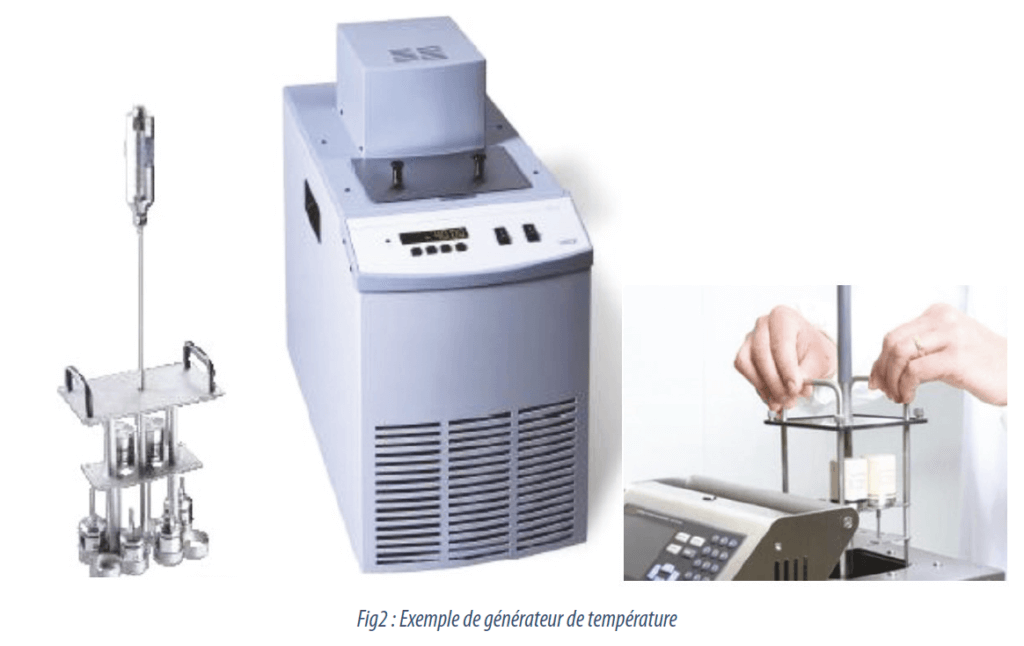
This solution offers the advantage of calibrating a plurality of probes at once and via appropriate software, it will do this in automatic mode (control bath, data acquisition the temperature of probe and calibration certificate generation).
The drawbacks to the use of the bath are:
- inertia in the raising or lowering temperature (depending on the volume and nature of the heat transfer fluid),
- cleaning of probes necessary due to the presence of oil,
- oil renew,
- follow rules EHS (SDS – Safety Data Sheet oils).
An alternative is to use a calibration oven. This technology allows a portable equipment, more flexible provided the use of sensors embedded with a sufficient cable length to reach the bottom of the insert well. The furnace is not suitable for short stems probes.
 | The use of a furnace can generate additional measurement uncertainties which must be taken account of having a calibration temperature sensing element and an electronic at room temperature. In this case, it will evaluate the effect of temperature on electronics. There is always an effect of temperature on electronics and this can be a source of uncertainty. It is recommended to have a comparative approach by evaluating the observed difference between a calibration with immersion probe and sensing element immersed only. Your supplier is able to give you an estimate of the impact of temperature on the electronics that will be expressed in +/- 0.001°C / °C for example. |
Example: if the difference between the calibration temperature of the sensitive element and the ambient temperature is 50°C – then we will have an impact of 0.05°C on our measurements.
4.2 The temperature of probe
 | The most critical during calibration is the standard probe that you will use to compare their values with those of your board sensors. It is essential to use a sufficiently precise probe and calibrated by an accredited laboratory. The level of uncertainty of the standard probe should be at least 3 times lower than that of your embedded sensors. With appropriate software, you can make your embedded sensors calibrations tethering COFRAC or equivalent on site. This method allows a moderate initial investment (Bath / Oven / sensor calibration) not to use the calibration service by an external laboratory, to have the metrological mastery of your embedded sensors internally and cost control. |
4.3 Other physical quantities
The set of recommendations, solutions and methods can also be applied to the pressure, relative humidity, CO2, H202 among others.
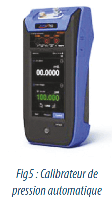 | Pressure Example: the steam sterilizer for which the combined study of the temperature and pressure indicates whether the conditions for obtaining a saturated steam are met. |
Relative Humidity
Regarding the relative humidity field calibration involves constraints in terms of budget and training (relative humidity generator, Stallion mirror -Hygromètre humidity).
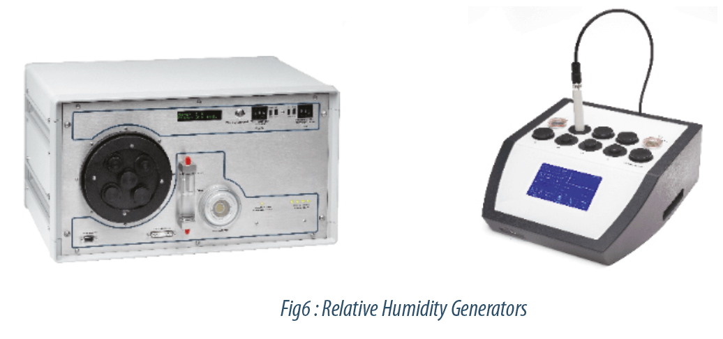
If the number of relative humidity sensors is a result and / or the high frequency of calibration, then it may be wise to make such an investment in staff and resources. Otherwise it is recommended to outsource this type of calibration in an accredited laboratory with a level of uncertainty.
The on-board probe is shown as the solution allowing a considerable saving of time during its implementation on the processes to be checked, but it is necessary for the calibration not to minimize the time. The risks of drift and maintenance linked to the factors of use are greater than it seems.
The training and experience should enable the user to control the drift of its sensors, optimize the durability and reliability of its embedded sensors in accordance with its demands quality / metrology.
Share article


Joel DA SILVA – KAYE
joel.dasilva@amphenol-sensors.com
Bibliography
ISO 14253-Part 1 standard, Specification area and compliance area
