Sommaire
- Annex1 & CCS → How to leverage mathematics & IT tools for driving improvement?
- CCS → Part 1. Deep dive on CCS understanding
- No detail left behind: A holistic approach to opening authorization in Sterile Manufacturing
- Production of incretin mimetics → Weight under control
- The next generation of reagents for Endotoxin Testing for the next generation of scientists in the pharmaceutical / medical device industry
- Le secret des produits pharmaceutiques et cosmétiques réussis, de la formulation à l'application
- A Toolbox for an Effective Technology Transfer
- Excess heat in pharmaceutical industry
Excess heat in pharmaceutical industry
The greater the number of waste heat recovery systems, the greater the efficiency of the total energy consumed. The best way to implement this recovery is to apply this cascade:
→ start by limiting waste heat ;
→ implement reuse through the same process ;
→ reuse elsewhere on the site ;
→ end with reuse on another site. In the following, I expand on different solutions for illustrating this approach.

Definition of waste heat
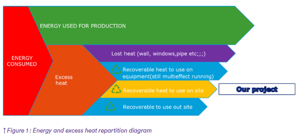
In industry, a small share of the total heat produced (in red on the graph) is used for production (in green on the image).
Waste heat is all the energy produced that is not used for direct production (orange part). There are different
categories of waste heat.Final waste heat (purple). The amount of this waste energy can be limited.
All other parts of the excess heat (light blue and yellow) can be reused in different systems in different ways:
• Recoverable by the same equipment
• Recoverable by a neighboring process
• Recoverable on other sites or in other industries
Pharmaceutical industry process
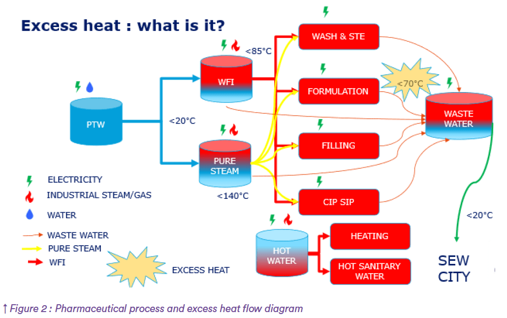
Thermal energy is used at various stages of production:
• To generate clean steam, used in manufacturing:
– for Sterilization,
– to clean in place/sterilize in place,
– for autoclaving.
• To produce water for injection, and to control temperature on the water distribution loop.
• To control temperature in production areas, whether classified or not.
• Control humidity in the production area.
Heat lost
The breakdown of these losses is as follows:
– Production rooms : To reduce losses, exterior walls must be insulated, and dedicated pharmaceutical walls and floors installed. Depending on exposure, windows and doors should be at least double-glazed, if not triple-glazed; the higher the Uw thermal efficiency, the better the insulation; for windows and external doors, we consider the airtightness index, known as AEV.
Thermal bridges must be avoided in construction design. It is paramount to pay attention to this when temperatures across adjacent rooms differ, e.g. cooling storage room with ambient storage room, or aseptic production room with technical room (e.g. HVAC technical room).
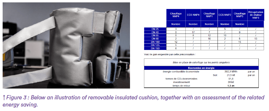
– The respective pipes of water network, cooling water, heat water, water for injection, industrial steam, clean steam, etc. Must be insulated, it is overall performed for fixed part but not for removable equipment parts that require to be accessible for maintenance : valve, steam trap, probes etc. These specific sections can be equiped with removable insulating cushion to limit lost heat
Loop back heat recovery (same process)
Once the first step has been taken, the next is to determine the possibilities for cold or heat recovery. This applies to air, water, smoke, etc.
Then it’s time to identify the various opportunities for reuse. Here are a few examples of industrial processes used in pharmaceutical plants.
For fossil fuel-fired boilers producing process steam, we can use the heat from the exhaust smoke to raise the temperature of the incoming water.
Another option is to use hot air, accumulated in the upper part of the room, to supply the air burner, thus improving boiler efficiency.
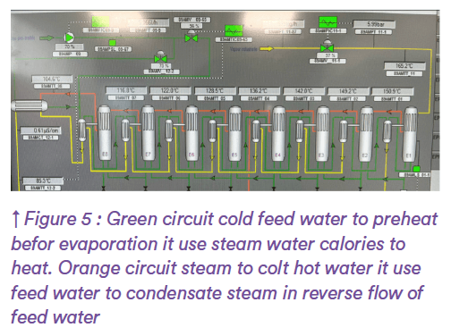
Where multi effect distiller is used to produce WFI, the same principle applies to a double flow system:
The last column is then supplied with cold pretreated water and the first column with industrial steam.Next, cooling energy from the supplied water is used to condensate the clean steam created in the first column and simultaneously heat from condensated water is used to increase temperature of pretreated water across the cascade columns In production area a part of the air energy is recovered in recovery. On average 90% of supplied air is recovered, the remaining 10% being fresh air, but where it comes to laboratories where chemical substances are in use, air recovery is banned, due to chemical risk for people, but we can then recover energy via an air exchanger plugged on the air exhaust, and next to transfer this energy towards the fresh air inlet.
Such recovery process allows for saving around 70% energy (heat or cold). Double flow HVAC system exists to exchange directly energy between fresh and exhaust air with the same efficiency (Figure6).
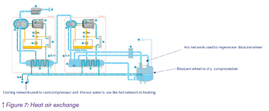
On the compressed air generator, the manufacturer uses the heat generated during the compression phase to preheat a water network used to dehumidify a desiccation wheel. The dehumidification wheel is one of the technologies available to treat the dew point of compressed air.
Many other solutions are available, to evaluate the possibilities, an energy flow diagram can be used while discussions with the equipment supplier(s) should be initiated to explore all the possibilities. (Figure 7)

Recovery by another process
To evaluate the possibilities, a flow diagram such as a Sankey chart can be used, this chart identifies the fluid inputs and outputs along with their enthalpic characteristics, resulting in highlighting possible heat recovery opportunities.
Regarding injectable production, water for injection is used at large to wash, rinse and for-mulate, the estimated final usage of water dedicated to the product itself ranges from 1 to 2 %, the remaining 98% being a low heat energy effluent, expected to be cooled before rejected to a public sewer network.
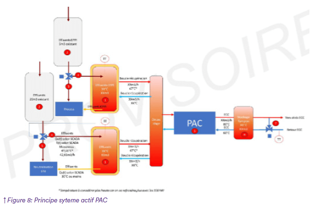
A first possibility, depending on the quality of low energy effluent, is to use it directly to feed a boiler, then both saving water and heat energy. Where this is not possible, low specific enthalpy effluent cooling can be achieved using a heat pump, for example, to supply energy to a hot water network, which is more effective when relative humidity control in aseptic environments is required, necessitating a year-round heating source. (Figure 8)
Other principles are applicable, previously we considered air compressor immediate reuse, however another recovery possibility is to use it to preheat a heat network. Notice that both energy recovery ways can be combined. Yet we first considered the recovery
possibilities associated with heat generating equipment, in the pharmaceutical industry the chiller system is widely used, both for air conditioning and for the process. A chiller, which is itself a heat pump, generates a lot of by-product energy.
With the help of equipment suppliers, we can use this generated energy to supply various heat networks.
Recovery reused on other sites
After exhausting all heat recovery options on site, often a part of the waste energy still remains. Then, based on the same assessment principle, it can be used by other companies, one possibility is to supply it to a public heat network to convey this heat to another site. Depending on season and usage this allows for saving energy.
All these recovery initiatives generate a decrease of energy usage and CO2 emissions, it is the first step of improvement, it enables a practical way to decarbonate energy, like using energy from wind farm, solar farm does.
The best energy is that which is not used, but as for the inevitable part that you do use, don’t waste it – that’s the mindset of lost energy recovering.
