


Sommaire
- Analytical Quality by Design: the required integration for Quality by Design
- Conception d’un isolateur de production. Du besoin utilisateur à la réalisation.
- Cahier Pratique – Essais de stérilité sous-isolateur – Qualification de performance et optimisation des plans de charge
- Advanced vaporized H2O2 decontamination technology for pharmaceutical isolators. Reduction of H2O2 decontamination cycle time using direct injection nozzles.
- Sécurisez le confinement de vos gants.
- Isolator Technology and Automation Enhanced Contamination Control in the Manufacture of Cell and Tissue Culture Derived Regenerative Medicine Products.
- The European approach to disinfectant qualification.
For the purpose of protecting pharmaceuticals from contamination with microbes or nonviable particles filling and closing machinery are equipped with isolators or other barrier systems. It is not only the Sterility Assurance Level (SAL) which is focused upon but also the non-productive time for decontamination processes between batches which has to be taken into account.
This article describes and evaluates a new technology to reduce the cycle time of isolators.

Different technologies are available and applied for protecting pharmaceuticals within aseptic processing. Aseptic filling lines use barrier systems in several ways.
Among those barrier systems isolators are characterized by their complete enclosing of the fill and finish unit, including areas like the Material Transfer Chamber (MTC) for introducing and removing items aseptically. Restricted access barrier systems (RABS) are divided into:
• Passive RABS (rigid housing, temperature control, laminar flow by the surrounding cleanroom,)
• Active RABS (laminar flow by proprietary ventilation units, HEPA filters),
• Active cRABS (separation of cleanroom venting and recirculating venting with the closed RABS, humidity control).
Restricted access barrier systems always have to be installed in a grade B cleanroom. Cleanrooms are divided into four grades: A, B, C, D. The grade D rooms have least amount of microbial contamination. The ISO 14644-1 norm divides cleanrooms into categories based on the amount of allowable particles per volume: ISO 1 to ISO 9, with ISO 1 being the purest. The air quality inside a RABS or isolator used for filling is designed to be grade A (ISO 5).
The air for RABS is usually supplied by the aggregates of the cleanroom. Since the physical separation between operators and interior of the isolators is significantly increased, isolators usually run under grade C (ISO 7) or D (ISO 8) cleanrooms.[1]
Nevertheless enclosing filling lines against environmental impact is not sufficient for producing aseptically. The contamination risk for finished products with microbes or nonviable particles has to be eliminated by implementing decontamination technology as a constitutive part of isolators.
Besides the conditioning systems for temperature and humidity an isolator therefore incorporates automated processing units for reproducible bio-decontamination (sterilization), mostly by using vaporized H2O2. Also, as previously mentioned, isolators require systems for the sterile transfer of products, primary packing materials and components into the machine housing.
Decontamination with Hydrogen Peroxide (H2O2)
Antimicrobial effects of Hydrogen Peroxide have been known since many years. The use of liquid Hydrogen Peroxide for decontamination has been established over the last two decades to become a standard method in the food industry but almost unknown in the pharmaceutical industry. Cleanroom decontamination is one of the major fields for disinfectants in the pharmaceutical industry and it is mainly performed using spray-on peracetic acid and vaporized formaldehyde.
With the “invention” of isolator technology for pharmaceutical aseptic filling the decontamination capabilities of Hydrogen Peroxide were (re-)discovered.
The use of Hydrogen Peroxide vapor has some great advantages compared to liquid spray on. Vaporized H2O2 can be distributed faster in a large volume and penetrates better than sprayed liquid. It also requires less aeration time, because less liquid has to be introduced into the volume.[2]
Aspects of time and residual concentration
Today the minimization of the contamination risk by the use of isolator technology is undisputed[3]. And while the decontamination effect of isolator technology has been accepted by regulatory authorities, isolator technology suppliers have had to face other challenges. First of all the time between the production of different batches was raised to several hours or even days by implementing isolators.
The unproductive time was the biggest reason for not introducing isolators at pharmaceutical companies.
The second challenge was (and still is) the residual concentration: H2O2 potentially affects the APIs in the pharmaceutical products. Therefore authorities recommend limits of time-weighted exposure between 0.5 and 1.0 ppm.
With the increase of biopharmaceuticals over the last years this process has been gaining a lot of attention. It is known that many protein-based pharmaceuticals react very sensitive to the exposure of H2O2.
Regarding the two mentioned items, several improvements have been achieved over the last years, and the use of isolators within the pharmaceutical industry has strongly increased[4]. Despite this increase, isolator suppliers are constantly being asked to reduce the H2O2 cycle time and at the same time reducing the residual concentrations.
One of the best known innovations today is the so called “catalytic aeration” which can be installed in an open-loop decontamination process and be retrofitted. Studies have been conducted examining the status before and after implementation regarding the cycle time and H2O2 concentration shift. It has been reported that after the upgrade of the catalytic converter the “total” decontamination cycle time from leak test to the completion of aeration was reduced to 2h 45mins from 5h30mins.
After the addition of the catalytic panels, a prolonged heated aeration phase was no longer necessary to achieve a vaporized H2O2 target of ≤ 1.0 ppm.[5]
Other pharmaceutical companies originally specified aeration to 0.5 ppm H2O2 but decided later to change the target down to 0.05 ppm using the same aeration parameters as prior the retrofit.
Further reductions: Development of the direct injection technology
A recently developed technology has proven to reduce the decontamination cycle even more than the above specified times. The idea behind it is the reduction of the injection time (D-value *). Therefore, the total aeration time and the total cycle time would be much shorter.
* D-value: According to DIN EN ISO 11138-1
A series of strategically placed nozzles above the CG-membranes, below the re-circulation filters, distributes the H2O2 vapor provided by an openloop generator. The desiccant is entering the isolator’s manipulation unit from top to bottom via the CG-membranes. Some air will penetrate the HEPA filters due to the lower differential pressure in the recirculation plenum. It is known that some plastic materials such as the HEPA filter compounding and the CG-membranes absorbs a bit of H2O2 during injection and desorbing slowly during aeration.
The combined distribution of H2O2 from above the CG-membranes as well as its direct injection is expected leading to improved results within the decontamination process. The new process involves introducing the H2O2 directly into the manipulation unit. The idea was to bring the H2O2 vapor closer to the point of use at potential worst-case locations thus creating turbulences within the isolator via the nozzles – without particle generation.
Within the first step of the new development the isolator supplier installed several of the H2O2 nozzles as usual within the CG plenum but added several nozzles as a bypass below the level of the CG membrane (figure 1) or above the filling machine. These developments were first conducted for sterility test isolators. Here, the general goals and requirements are the same as for production isolators: decontamination time savings and minimized residual concentrations. The additional direct injection nozzles led to very promising results.
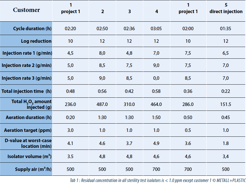
The data in table 1 represents a comparison between different sterility test isolators from the same supplier. The sterility test isolators are installed at several companies (“customer 1” runs two different sterility test isolators from the same supplier). “Customer 5” is the first company which installed the new direct injection technology in its first version.
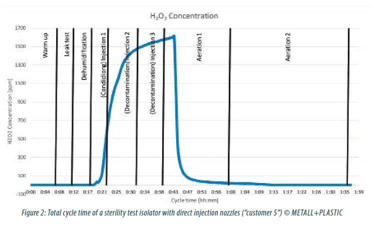
The acquired data of “customer 5” represents the first version of the newly developed system. A positive impact of the direct injection nozzles is obvious. Although the presuppositions – for example the volume of isolator – differ between the analyzed customer installations, the data gives an impression about potential savings in H2O2 injection volume, D-values and total cycle time by incorporating the new technology. Figure 2 gives an overview about the complete decontamination process at “customer 5”.
With these results in mind the question was if the positive impact of a combined direct and indirect injection – better turbulences and reduced H2O2 consumption resulting in reduced cycle time – could be even further improved? The purpose of the development process was now to analyze the best position of the direct injection nozzles.
Experienced pharmaceutical engineers know about the influence of the geometry of the manipulation unit, the installed and the adjoining systems and how they influence potential worst case BI locations and therefore the whole decontamination process. So the arrangement of the H2O2 injection nozzles was based on geometric aspects of the filling machine and the isolator to get a faster kill on biological indicators (BIs). The assumptions of the developers were checked within in a simulation model. Finally, the combined knowledge led to general conclusions about the best positions of the direct injection nozzles.
For every project, the final position of the direct injection nozzles has to be defined depending on the individual geometry of a filling and closing machine. Nevertheless it can be said:
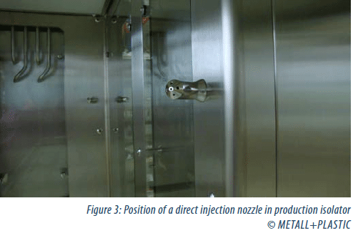
• In comparison to the first version, some direct injection nozzles are now placed within the manipulation unit much closer to the machine and its base plate (figure 3).
• A typical position of direct injection nozzles is within the corners of the manipulation unit – about half way between the machine base plate and the CG membrane.
For the supply of H2O2, all additional piping could be installed within the double walls of the isolator. The design process also had to consider the distribution of vaporized H2O2 in terms of volume and velocity (pressure) at the different nozzles for the whole system. Therefore, all pipe installations within the isolator, together with the analog dampers and the control system, were completely redesigned.
• Within new projects the air flow towards the CG-plenum and the manipulation unit can now be adjusted separately via programmable setpoints.
Furthermore, the geometry of the nozzles themselves were optimized by the engineers in order to create a reliable and safe decontamination processes with less H2O2 consumption and shorter cycle times.
Evaluation of the final design
Meanwhile, the general design for the direct injections nozzles and specifications for new projects are defined. An internal study has been conducted – this time for a production isolator following the new design principle. It has to be pointed out, that the acquired data describes a decontamination process of an isolator that lacks a filling and closing unit, a robot, a transport rake and other equipment which will strongly influence the final (validated) decontamination cycle. At this stage it was the only feasible way to generate data for the new developed system – and to compare this data to the same isolator without direct injection nozzles.
The test design evaluated a “real” isolator, built for a customer, and which will be soon “integrated” with a “real” filling and closing machine. It was possible to test this isolator first without the direct injection filling nozzles. Later these results were compared with the data of the same isolator, now incorporating the new direct injection nozzles.
The results are:
• Reduction of the H2O2 injection phase (10-log spore reduction, residual concentration < 0.5 ppm [detected by Draeger sensor])
• from previous 57 minutes to 33 minutes ( → -42%)
• Reduction of the total H2O2consumption
• from previous 773.0 g to 437.0 g ( → -43 %)
• Reduction of the aeration time due to shortened H2O2 injection phase. Total cycle time: < 1.5 hours at ≤ 0.5 ppm.
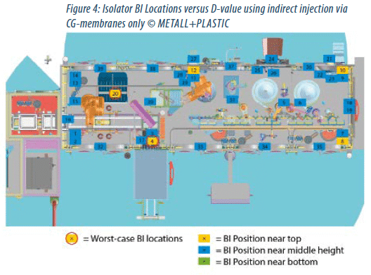
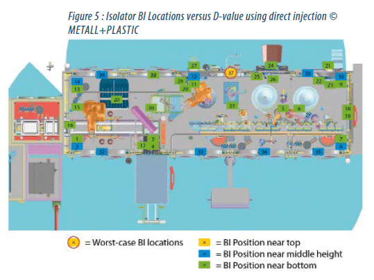
The efficacy can also be illustrated by the comparison of the D-values for 39 identical BI locations within the manipulation unit. Figure 4 shows the isolator using previous technology, figure 5 the same isolator using direct injection nozzles. (Note: the filling and closing system, the rake, robot and other devices are shown only for illustration purposes. None of the mentioned devices were installed while determining the D-values.)
Using the previous technology, the mean system D-values were determined by the worst-case locations 4 and 20 and a mean system D-value of 5.2 minutes and 5.7 minutes.
The worst-case location within the isolator incorporating the direct injection nozzles switched to BI location 37. Here, the mean system D-value was 3.3 minutes. It is also interesting to see that in the first illustration none of the BIs achieved the “green” status (D-value < 2.0 minutes), but 6 locations are marked yellow (D-value > 3.0 minutes).
In figure 5, representing the data of the direct injection nozzles system, most of the BIs are “green”. Only one location (BI 37) has the yellow status.
Furthermore, the new worst-case location shows no risk of potential product contact.
Conclusion
Safe, stable and reproducible are the main advantages associated with isolator technology today. While retaining all these positive aspects suppliers of isolator technology address the reduction of unproductive time, the cycle time. For a few years, with the increasing advent of biopharmaceuticals, this goal is gaining further importance as the sensitivity of those protein-based pharmaceuticals against H2O2 led to very small residual concentrations in the specifications of many projects.
Today, values of < 0.5 ppm are almost common.
The positive impact of a new technology using direct injections nozzles for H2O2 within the manipulation unit could be evaluated first by comparison of the data of different validated sterility test isolators. One of them incorporated the first version of the H2O2 direct injection system and it showed significantly reduced cycle times. Secondly, a production isolator (at an early stage – without adjoining systems) was tested: It showed the achievement by incorporating the direct injection in comparison to the identical production isolator without direct injection. This data represents the final design of the direct injection nozzles.
An important positive side effect of the new technology is the reduced consumption of H2O2 which means reduced stress on the surfaces of the filling and closing machine.
The direct injection system (DECOjet®) can be retrofitted into isolators following the open loop and double walls design.

Stefan KLEINMANN – METALL+PLASTIC
Stefanb.Kleinmann@metall-plastic.de

Matthias SCHEU – METALL+PLASTIC
Stefan.Kleinmann@metall-plastic.de
Partager l’article
Références
[1] European Commission – Enterprise and Industry Directorate-General: “EU Guidelines to Good Manufacturing Practice Medicinal Products for Human and Veterinary Use” (2008) Annex 1, Manufacture of Sterile Medicinal Products (corrected version), page 6
[2:] Dissertation ETH No. 14044; A. C. Sterchi: “Hydrogen Peroxide in Pharma-Isolators, Investigations about Behaviors, Measurements and Effects” (2001), page 1
[3:] U.S. Department of Health and Human Services, Food and Drug Administration: “Sterile Drug Products Produced by Aseptic Processing – Current Good Manufacturing Practice” (2004) Appendix 1, page 48
[4] Pharmaceutical Technology, Supplement, Issue 6; Maurizio Battistini: “Manufacturing High-Potency Drugs Using Isolators“ (November 2008); http://www.pharmtech.com/manufacturinghigh-potency-drugs-using-isolators?id=&pageID=1&sk=&date=
[5] Pharmaceutical Engineering; Donald Edington, John Lanier, Michael Walsh, Stefan Kleinmann: „Case Study: Implementation of Catalytic Technology to Improve the Aeration Process for a Syringe-Filling Line Isolator“, (January-February 2016) page 74
