


Summary
- Three steps to contamination control when utilising single use equipment
- Automatic Particle Measurement in Hot Air Sterilizing Tunnels
- Hydrogen Peroxide Sterilization and Isolator Connections through a Magnetic Driven Door For Innovative Lay-outs in Aseptic Processes
- Fast X-Ray Tomography Techniques : ready for new Pharmaceutical Applications ?
Automatic Particle Measurement in Hot Air Sterilizing Tunnels
The regular monitoring of cleanrooms and installed HVAC systems plays a central role in the sterile processing of pharmaceutical products because any faults occurring here can have a direct effect on the quality of the processes and products. The applicable statutory requirements are therefore highly stringent. The test procedures prescribed for systems of this type, such as the filter integrity test, involve numerous processes which are still done manually.

If these processes are also automated, process reliability will be significantly higher and test results more easily reproducible. One such automated solution is now available for filter integrity testing in hot air sterilizing tunnels: a measuring instrument that is integrated directly into the tunnel’s control system. This innovative system sets new standards in filter integrity testing.
Sterile and pyrogen-free glass containers are a basic requirement for GMP and FDA-compliant production. Hot air sterilizing and depyrogenating tunnels of the DHT series are used specially for this purpose. After entering a DHT, cleaned containers are transported in an upright position through all three work zones in the tunnel: pre-heating zone, sterilizing zone and cooling zone. The containers are sterilized to exact specifications using hot air (dry heat). Viable microorganisms and pathogens are reduced by more than six powers of ten (6 log) [4].
However, inert residues, such as endotoxins, spores or dead cellular fragments (so-called pyrogens), can also trigger an inflammatory immune reaction if they enter the bloodstream parenterally. To remove any inert residues adhering to the glass surface, the containers are depyrogenated. In order to achieve a 3 log reduction, a temperature of at least 250 °C must be reached inside the glass container [4] [6].
By doing so, the requirements for sterilization will also be met. The pyrogens (particles) loosened during depyrogenation are filtered out of the air flow using class H13 or H14 particle filters.
In order to meet the mandatory requirements for cleanroom class A within the DHT, it is essential that the filters used in the process work perfectly.
Regulatory requirements
Annex 1 to the EU GMP Guide governs the sterile processing of medicinal products [1]. Here it is stated under the general requirements that an appropriate level of cleanliness should be maintained in cleanroom areas and that ventilation should be provided using filters of adequate effectiveness. Item 97 stipulates explicitly that the air must pass through a HEPA filter. As to filters, Annex 1 refers indirectly to the requirements as defined by ISO 14644-2 [7].
The current draft revision of Annex 1 is more specific in this regard; under the heading “Dry Heat Sterilization”, it states: “All air supplied to the tunnel should pass through a HEPA filter; periodic tests should be performed to demonstrate filter integrity”. [ 1a: (8.65 Lines 1165-1167)].
An overview of the key specifications for filter tests can be found in Table 1 and Table 2 (Kuhn & Moschberger, 2013) [3].
ISO 14644-3 deals in Annex B with test procedures that can be used to characterize a cleanroom as described and defined in other parts of ISO 14644 [8] [9].
Leak test using optical particle counters
Basically, these regulations allow for two possible methods: 1, testing with optical particle counters; and 2, testing with aerosol photometers. The method described here utilizes optical particle counters because, among other things, this allows even small leaks to be detected and particle sizes to be determined.
Put simply, the procedure involves admitting a defined number of particles into the sterilizing tunnel on the non-sterile side above the filter. A particle count is taken both here and on the sterile side below the filter in order to check the filter for integrity. To this end, the entire surface of the filter has to be scanned with a probe (cf. Figure 1).
The particles are admitted using an aerosol generator which applies an aerosol (usually DEHS – diethylhexyl sebacate) on the air inlet side of the filter. It is important to ensure that the particle distribution is homogeneous. The number of particles on the raw air side (upstream) with a dilution factor of 1:10 or 1:100 is monitored throughout the measurement process using a particle counter and is corrected if required. The necessary concentration of the aerosol load for each filter type is explained in depth in the standard and will not be explained in any further detail here. The filter medium, the leakproof filter mounting and the filter frame are then scanned using an isokinetic sampling probe and an additional particle counter on the sterile air side (downstream). The particles which have not been separated by the filter medium or retained by the filter seal and filter element are detected by the particle counter and counted according to their size.
If a significant (abrupt) increase in particles is detected at certain points, this is indicative of potential leaks. If such positions are detected, they are examined more closely by re-measurement. These measurements are taken continuously in order to be able to make a definite assessment of the increased concentration found and the possible leakage. If the particle count exceeds a predetermined limit, a leak is determined at this position.
To ensure that the measurement is as accurate as possible and that the (continuous) scan and the re-measurement are reproducible on the sterile air side, several parameters must be observed.

A feed rate of 8 centimeters per second should not be exceeded during the scanning process – 5 centimeters per second is standard practice. The entire air outlet surface is scanned in overlapping tracks. The max. distance from the probe to the filter/air outlet surface is 3 centimeters and the max. sampling volume is 1 CF/min (28.3 l/min). Depending on filter discharge velocity, probe geometry, probe inlet surface area and the particle load on the raw air side, the feed rate must be reduced accordingly [8]. This is clearly asking a lot of the operator. The probe is attached to a rod which the operator must guide precisely and .at an exact speed under the filter (Fig. 2)
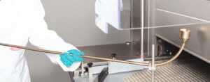
The manual process: operator-related inaccuracies
“The manual scanning process can give rise to operator inconsistencies that can influence the measurement” [cf. 8].
The wider and longer the tunnel, the more difficult it is to precisely scan the filter surface. In their risk assessment of individual scanning parameters during manual leak testing, M. Kuhn et al. have concluded that the manual method involves a high risk of error, particularly with respect to the overlap of the scanning tracks. When the probe is guided manually, the scanning tracks will not be straight. The smaller the selected overlap, the greater the probability of missing filter areas in between adjacent scanning tracks (according to Kuhn et. al., the scanning tracks will be wavy to a greater or lesser extent depending on how accessible the filters are and how long the measurement takes). They also rate the impact of this inaccuracy as high: “Leaks in these areas will not be detected. This means that leaks can exist that are far larger than the defined nominal leaks [3].
The newly developed LinearTwinScan measuring instrument is automatically guided through the sterilizing tunnel by the tunnel conveyor belt and represents a significant process improvement. This was achieved by integrating the automated measuring system into the sterilizing tunnel control system during the service phase, which is why this system was developed in close collaboration between the tunnel manufacturer and the measuring instrument manufacturer (Fig. 3).
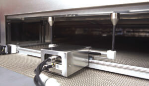
To minimize the number of moving parts, LinearTwinScan is equipped with two particle counters which measure the entire filter area, including the edge areas of the hot air sterilizing tunnel. The measuring unit is transported longitudinally by the tunnel conveyor belt at a defined feed rate.
. The measuring carriage runs transversely on a linear track (Fig. 4).

The operator can monitor the progress of the measurement on a tablet PC, the data being transferred and visualized in real time. Areas where elevated particle concentrations are measured are marked red. (Fig. 5)The particle concentration at these points is selectively re-measured as described above. This allows for much more accurate measurement and re-measurement than would be the case with the manual method. The distance between the filter and the measuring probe and the speed at which the measurement is taken meet the normative requirements exactly and are documented during the measuring process. The danger of parts of a filter not being scanned is also eliminated.
However, automated particle measurement has other advantages, too.
In the manual process, the number of particles on the “non-sterile” side of the filter surface is monitored by the operator using the aerosol generator and adjusted manually if necessary. In the automated process, the measuring instrument and aerosol generator are networked with each other. For instance, the particle concentration is automatically readjusted and the measuring process is automatically aborted if the preselected particle concentration on the raw air side deviates by more than ±15 % from the mean value.
Another important advantage is that data can be acquired more easily. In the manual process, the measuring instrument prints the measurement results on thermal paper and the operator transfers the data manually to the appropriate test reports.
With the new automated process, the measurement results are processed electronically and visualized on a so-called heat map. Data is processed in accordance with FDA 21 CFR Part 11 [5] or [2]. The data obtained in this way can be stored and, if necessary, processed subsequently.
In principle, all measurement and re-measurement parameters in the ScanWare can be customized by the operator and by the user in a template (.ini file). As a result, the system is adaptable to non-standard SOP requirements. When the system is handed over to the user or service provider, these parameters must be agreed in writing with the manufacturer and stored in the system’s CBOX.
Conclusion
Thanks to its integration into the sterilizing tunnel control system and its automatic measurement capability, LinearTwinScan delivers precise and reproducible results that are immediately available in the test report.
The automatic measurement process meets the requirements of DIN EN ISO 14644-3 and, unlike the manual measurement process, provides reliable values with respect to measurement speed and ensures that a constant distance is maintained between the probe and the filter surface. It also makes sure that the entire surface of the filter is scanned. The process is not dependent on the size of the hot air sterilizing tunnel.
The measurement data is analyzed and evaluated in real time while the automatic measurement is in progress. This means that results and electronic test reports compliant with FDA and GMP guidelines are available as soon as this process is completed.
The potential applications have by no means been exhausted yet. In future, the LinearTwinScan system will be upgraded to include additional measuring equipment that can be used to precisely determine the air flow velocity and the cleanroom class of the sterilizing tunnel.
Share article


Daniel ENGEL – BAUSCH+STRÖBEL
Daniel ENGEL has been responsible for the qualification of UDAF and barrier systems at Bausch + Ströbel Maschinenfabrik Ilshofen since 2013. After training as a process mechanic for plastics and rubber technology and subsequent further training as a state-certified mechanical engineer, he worked for 8 years at Rommelag CMO (formerly Holopack Verpackungstechnik GmbH). He was responsible here for project planning and qualification in the areas of water and steam treatment as well as batching systems.

Christian DORFNER – INFRASOLUTION GROUP
Christian DORFNER is currently responsible for R&D and Production at the InfraSolution Group. He studied space and aeronautical engineering at the University of the Federal Armed Forces in Munich and holds a doctorate in aero engine design from the German Aerospace Center in Cologne. He served 12 years as a technical and armaments officer in the German Air Force and worked for notable corporations including AIRBUS Defense & Space as well as SMEs and start-ups in various roles and responsibilities. As a PMP certified manager, he brings experience from many international projects across various industries such as aerospace & defense, robotics and cleanroom technology.
Glossary
HVAC: Heating, Ventilation and Air Conditioning
DHT : Hot Air Sterilizing and Depyrogenating Tunnel
HEPA Filter: “High Efficency Particulate Air Filter”
SOP : “Standard Operation Procedure”
Bibliography
(1) Guide EU-GMP ANNEXE 1 : Fabrication de médicaments stériles (édition mars 2008)
(1a) Nouvelle édition cosignée par l’EMA depuis le 31.05.2015 https://ec.europa.eu/health/sites/health/files/files/gmp/2017_12_pc_annex1_consultation_document.pdf (dernière consultation le 7.5.2019)
(2) COMMISSION EUROPÉENNE Direction de la santé et des consommateurs. (2011, 08). Extrait de l’annexe 11 des BPF de l’UE – Systèmes informatisés : http://academy.gmp-compliance.org/guidemgr/files/ANNEX11_01-2011_EN.PDF
(3) Kuhn, M., & Moschberger, U. (12. 11 2013). Consulté le 15.05.2019 à partir de “Test d’étanchéité des filtres : analyse des sondes d’échantillonnage mobiles” https://www.reinraum.de/news.html?id=2276
(4) PDA – Parenteral Drug Association, Inc. (2013, 09). Technical Report No. 3 – Validation of Dry Heat Processes Used for Depyrogenation and Sterilization. Bethesda, USA: Parenteral Drug Association, Inc. Retrieved from Guidance for Industry – Sterile Drug Products Produced by Aseptic Processing.
(5) U.S. Food & Drug Administration (FDA). (2019, 05 14). (U. F. (FDA), Editor) Retrieved 05 15, 2019, from eCFR – Electronic Code of Federal Regulations – Title 21: https://www.ecfr.gov/cgi-bin/text-idx?SID=3ee286332416f26a91d9e6d786a604ab&mc=true&tpl=/ecfrbrowse/Title21/21tab_02.tpl
(6) ISO 11139 :2018 Stérilisation des produits de santé – Vocabulaire des termes utilisés dans les normes de procédés de stérilisation et les équipements connexes
(7) DIN EN ISO 14644-2:2016, Salles blanches et zones de salles blanches associées, Partie 2 : Surveillance pour le contrôle de la pureté de l’air en salle blanche sur la base de la concentration de particules.
(8) DIN EN ISO 14644-3: 2006 Salles blanches et salles blanches associées, Partie 3 : Méthodes d’essai ; version allemande EN ISO 14644-3.2005
(9) Kopf, Markus: „Contrôles d’étanchéité sur le système de filtration intégré selon la norme DIN EN ISO 14644-3: 2006. Contexte réglementaire, théorie et pratique de la métrologie. Dans la newsletter Reinraum Online, édition DE-08-2018 p. 7/86
