
Summary
- ASTM E2500 : let's cross the Bridge !
- From study of the context to use of appropriate water treatment technologies
- A new water management strategy for the pharmaceutical industry
- Continuous measurement in water for pharmaceutical use (WPU)
- Candida auris, an emerging pathogenic “killer” species
- Cleaning and disinfection program part of the lifecycle approach: a risk based rather arbitrarily imposed approach
- Pharmaceutical water: the inside story of installation maintenance
- Pharma & the New Healthcare Economy. Ready or not ?
Tests conducted on water for pharmaceutical use fall within a regulatory context dictated by pharmacopoeias and Good Manufacturing Practice guidelines (French BPF and GMP). Instrument manufacturers have worked to develop efficient online analyzers to perform continuous monitoring of certain parameters. These instruments have been known for a number of years but are not always used.
Hence Annex 15 of Good Manufacturing Processes and the PAT (Process Analytical Technology) working party tend to favor the continuous analysis of key parameters, since these enable round-the-clock monitoring and lead to greater responsiveness in the event of drift. These measures make it possible to continuously validate the quality of water for pharmaceutical use in distribution systems or loops.
We will examine the key parameters in WPU distribution loops and conclude with aspects related to the water intended for human consumption (potable or drinking water) entering the plant. The pharmaceutical industry must know and control the quality of this drinking water since it is a key factor determining the quality of the water for pharmaceutical use and the treatments to be applied.
1. Key parameters
Conductivity
Total Organic Carbon (TOC)
This is a non-specific indicator of organic pollution. TOC can be defined as a source of nutrients for the bacteria that could develop in WPU loops (biofilm). It is organic matter from “living organisms”. Sometimes the contaminants come from the decomposition of materials contained inside WPU distribution loops. The major risk is the development of a biofilm inside cold WPU distribution loops, particularly due to back contamination. Certain cold points of use of hot WPU water distribution loops can also be contaminated.
Ozone
This is a powerful oxidant used to sanitize cold bulk purified water distribution loops, primarily to prevent contamination and, in extreme cases, to destroy a biofilm.
2. Measurement principles
2.1 Principle of conductivity measurement
The measurement of conductivity is related to Ohm’s law:U = R x I, U being the voltage in volts, R the resistivity in ohms and I the current in amps. The conductivity C, expressed in Siemens per centimeter, is the result of the following equation:
C = k x G, where G is the inverse of the resistivity expressed in Siemens, andk, a constant expressed in cm-1. This constant k is a value related to the composition of the measurement electrode: it is the ratio between the distance separating the electrodes and their surface area: k = distance ÷ surface area

The conductivity of a solution depends on:
- its ionic concentration
- the valency of the ions
- the nature of the solution (acidic, basic or neutral)
- the temperature.
Hence the conductivity related to the temperature indicates the total mineralization status of water. Since the curve is not linear, it is not sufficient to introduce a correction coefficient.

a) Application
In practice, for online measurements, manufacturers have developed sensors that are usually composed of two electrode made of noble metals (stainless steel 316, titanium, platinum, etc.) in accordance with then principle outlined above:
An alternating voltage is applied to the electrodes in contact with the solution to be tested. The conductance is used to calculate the conductivity, concentration or specific resistivity of the solution.
This is a very effective method for measuring low conductivities. In pharmaceutical applications, the cell constant must be certified at +/- 2%. The measurement resolution must be at least 0.1 μS /cm. And the measurement is always performed without any compensation related to temperature, with pharmacists preferring to use raw values.

b) Verification
Control of the cell constant may be performed either directly by measuring a solution of certified conductivity (a calibrated standard) with the sensor, or indirectly by comparing the analyzer results (with its cell) and the results obtained with an analyzer for which the constant is certified. This is known as a “secondary standard” analyzer, itself associated with a “master standard”.
Chapter 645 of the USP defines a three-stage test (not described in this article) to make sure that the conductivity of the water clearly complies with the quality limits.

In practice, the indirect method is very easy to implement because a cell can be certified without dismantling the sensor in place, and it can be used to control the whole system at the same time (transmitter, sensor and cable). It is also possible to verify the transmitter and cable only, using certified test resistors.
In practice, when verifications are erroneous, the only option available to pharmacists is to adjust the cell constant. However this makes no sense given the meaning of the word “constant”. Logically, the sensor that is drifting should be replaced or cleaned, because the only explanation for this drift can be clogging or, in the worst case scenario, an intrinsic modification in its geometry due to deterioration of the electrode itself.

c) Where are the measurements taken?
The online measurement points are the inlets and outlets of the WPU production system and, obviously, loop starts and returns.
2.2 Principle of Total Organic Carbon (TOC) measurement
The principle for measurement of TOC in water for pharmaceutical use is indirect (distribution loops). TheTOC is determined by subtracting the total inorganic carbon (TIC) from the total carbon(TC):
![]()
To differentiate between carbon species, it is necessary to break down the TC, to obtain the proportion of TIC.
Today, the following main methods can be found on the market for determining TOC:
- Thermal oxidation with infrared detection (NDIR) (NON-DISPERSIVE INFRARED)
- Coupled chemical and irradiation oxidation (persulfates and UV) with NDIR detection, or detection by conductivity
- Direct UV oxidation with detection of conductivity
Oxidation
In thermal oxidation processes, the organic compounds are broken down at high temperature. Hence undissolved components (solid matter or materials from abrasion) can also be completely broken down into CO2.
In applications with high organic loads (for example municipal wastewater), this is a tried and tested method.
In coupled oxidation processes, the components are broken down by a powerful oxidant, such as persulfate, as well as UV radiation. This enables a broader scope of application [less than 1 ppb (μg/L) to more than 100 ppm (mg/L)]. However, it requires chemical products of high purity and a purge gas, which are not insignificant factors in terms of cost.
In UV lamp oxidation processes, only the lamp’s radiation is used to break down the carbon matter. This implies a lower measurement range and a low-conductivity sample. However, for applications in pure and ultra-pure water, this method is reliable and less expensive.
Detection
NDIR detection : This method employs an infrared detector that measures the CO2 generated by determining the amount of infrared light absorbed by CO2 at a known distance.
Detection by conductivity sensor : the CO2 generated has an impact on conductivity, increasing its value. The calculation is made using known conversion tables.
In the pharmaceutical industry, the regulations are stipulated by pharmacopoeias:
- US Pharmacopoeia, TOC: USP 643,
- European Pharmacopoeia, TOC: EP 2.2.24,
- Japanese Pharmacopoeia, JP,
Since TOC is a nutrient for bacteria, it goes without saying that water for pharmaceutical use included in the composition of medicinal products must be free of TOC in order to prevent bacterial proliferation and the development of a biofilm.

a) Application: UV/differential conductivity method for monitoring a purified water loop
In this process, the online analyzer sucks in the sample from the loop. After the first conductivity measurement, the sample enters a UV reactor. Inside, the organic carbon present in the water for pharmaceutical use is oxidized into CO2. This CO2 in turn increases the conductivity measured. This conductivity is measured by a second sensor positioned after the UV reactor.
The difference between the second and the first conductivity measurement can be used to calculate the TOC on the basis of the following principle:

This recognized method is the simplest and the quickest. The response time is less than 2 minutes. Monitoring of the process is continuous, making it possible to control the WPU distribution loop. This type of equipment is an economical choice because the investment, operating and maintenance costs are very reasonable.
The scope of application of this operating principle is only useful for pure and ultra-pure waters in which the conductivity is less than 2 μS/cm at 20°C. This measurement principle is very well suited to water for pharmaceutical use. The difference between the TC and TIC is substantial. The TIC is not very high and is essentially composed of CO2, leading to reliable results over the range 0 to 1000 ppb.
b) Verification
The monographs also define criteria for measurement calibration. This article does not describe all the methods, but for the manufacture of certified measurement calibration and validation solutions:
- the equipment must be calibrated: using a standard solution
- the limit of detection must be less than 50 ppb
- the determination of TOC must be performed by subtracting TIC from TC
- a crucial parameter: the SST (System Suitability Test) must be performed every 6 months.
This test verifies that the analyzer is capable of oxidizing both single and complex bonds:

To perform the SST, we will use solutions of sucrose (single bonds) and 1,4 benzoquinone (complex bonds) giving TOC responses = 500 ppb +/- 15%. The water used to prepare these solutions is described as “blank”.
The success of the test is expressed in relative efficacy:
- Response of the water blank rw = < 100 ppb COT
- Response of the standard solution 1 rs: sucrose RS at 500 ppb TOC
- Response of the standard solution 2 rss1,4-benzoquinone RS at 500 ppb TOC

The test is successful if the result is between 85 and 115%. We thereby ensure the suitability of the analyzer and it is consequently validated.

In practice, this test is performed every 6 months, with maintenance also performed at the same frequency.
- Performance of the SST to ensure that the previous 6 months are validated.
- Performance of maintenance, replacement of recommended components, such as the UV lamp, for example.
- Performance of full-scale calibration on the whole analyzer (optional but recommended).
- Performance of the SST for validation and start of the next 6-month period.
c) Where are the measurements taken?
The characteristic points to be monitored are:
- the WPU distribution loop return
- the performance of measurements at distiller exits may be recommended but especially at ion exchange resin exits.
2.3 Principle of ozone measurement
Rappel USP- NF 24<1231>
“Chemical additives are used in water systems to control microorganisms by use of sanitizing agents, such as chlorine compounds and ozone… These additives do not constitute “added substances” as long as they are either removed by subsequent processing steps or are otherwise absent from the finished water. Control of additives to ensure a continuously effective concentration and subsequent monitoring to ensure their removal should be designed into the system and included in the monitoring program.”
A continuous ozone analyzer checks:
- the amount of ozone introduced at the UV generator entrance
- the absence of ozone at the UV generator exit (UV operating)
- measurement of the amount of ozone in the distribution loop return (UV stopped).
The measurement principles used are the electrochemical method and the spectrophotometric method.
a) Amperometric sensor principle / method
The first method uses amperometric sensors operating on the basis of the following principle:
- gas is dissolved and diffused through the membrane then the electrolyte
- reduction reaction on the cathode = production of ions
- the current induced is proportional to the O3 concentration3

The sensitivity of the amperometric (electrochemical) sensor is good. If no current is induced, there is no ozone. The major drawback of this technology is related to polarization and depolarization phenomena.
The steady presence of ozone is required to polarize the sensor. Electrochemical measurement (amperometric sensor) presents a major reliability disadvantage concerning measurement of ozone absence. The sensor is quickly depolarized and it constantly needs to be “shown” the ozone, requiring automated systems with all the associated costs.
The fact that low ozone values are measured with this type of sensor has a significant impact on response times, which are prolonged.
An additional disadvantage is that of maintenance (replacement of the membrane), making it necessary to interrupt measurement and perform a calibration and polarization procedure, which takes time (sometimes as much as 4 days).
b) Verification for amperometric methods
The zero is determined in air (along with a control of pressure and temperature), using the principle of the O2/O3 ratio, assumed to be constant. The ozonizer is then switched to forced-mode operation to reach a value of at least 100 ppb, controlled using a reference method. The reference method is spectrophotometry.
c) Spectrophotometric measurement principle / method
All the above disadvantages are eliminated if a direct online spectrophotometric method is used for the analyzer.
This method is the standardized reference method for ozone measurement, using DPD-IODIDE, in accordance with DIN-38408-3.
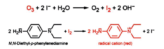
In the presence of ozone, the addition of these reagents to the sample causes a color to develop, measured by the spectrophotometer. The intensity of this color is directly proportional to the ozone concentration.
No color = 0 ozone and the precision is 1 ppb.
The disadvantage of this method is that it uses specific reagents, but guarantees a much more reliable ozone measurement and, above all, guarantees the measurement of absence since there is no depolarization.
d) Verification for spectrophotometric methods
The metrology is much simpler since all that is required is to place secondary standards in the photometer to perform full-scale calibration. A low range point and the zero are determined before each measurement.

There is no time wasted following maintenance on this instrument since there are no polarization phenomena. The measurement is reliable from the very first measurement.
However, it is necessary to specify an essential point for the measurement of ozone:
Water sampling
- the water must be moving
- avoid degassing points:
- suction from a pump or after a valve
- at a bend or low point
- at the top of a horizontal pipe
- vertical pipe
There are no regulations concerning ozone testing but recommendations exist:
- ISPE recommendation for disinfection (20 ppb < O3 < 200 ppb).
- SWAN recommendation (10 ppb < O3 < 30 ppb).
- the ozone measurement at the UV generator exit is between 0 ppb and 5 ppb.
c) Where are the measurements taken?

Conclusion
Continuous measurements of these different parameters are qualitative and economic advantages. These measurements make it possible to continuously guarantee the quality of water for pharmaceutical use and enable greater responsiveness.
Given the cost associated with nonconformities and the time needed to manage them, there is no doubt that these online testing systems are now essential for the management of installations.
It should be recalled that potable or drinking water (intended for human consumption) entering the site is the site’s responsibility. We can already consider that drinking water is a water for pharmaceutical use since it supplies the whole site.
The site must have regular tests performed by approved laboratories and must monitor a few parameters:
- Measuring chlorine at the point of entry into the plant is important in order to know whether the risk of contamination is controlled further upstream, but also in order to define chlorine elimination systems downstream. Chlorine needs to be eliminated in order to protect reverse osmosis membranes and electrodeionization systems, which are damaged by residual chlorine.
- Installing an analyzer to verify the total absence of chlorine before membranes is an economic advantag, given the cost of reverse osmosis membranes and, above all, electrodeionization systems.deionization.
- Turbidity (although not a real index of water clogging) can be a good indicator to avoid clogging of reverse osmosis membranes in the event of any upward drift inturbidity
- Conductivity is an indicator of the ionic load of drinking water.
- Hardness may also need to be monitored depending on the purification treatment.

Benjamin GRACIA – SWAN
Trained in the water trades and related components such as electrical engineering and civil engineering infrastructure, he began his activity in industry, for more than 5 years, at Suez and OTV, in various operating services and work supervision. He was faced with a number of issues related to water quality and the importance of analytical tools. In 2010, he joined Swan France Instruments d’Analyse, as a project manager and then responsible for key accounts. In this context, he actively participates in the development of the pharmaceutical market.
benjamin.gracia@swan-france.fr
Share the article
Bibliography
USP<643> “Total Organic Carbon”, United States Pharmacopoeia 36-NF 31, U.S. Pharmacopeial Convention Inc., Rockville, Md. (2013).
USP<645> “Water Conductivity”, United States Pharmacopoeia 36-NF 31, U.S. Pharmacopeial Convention Inc., Rockville, Md. (2013).
USP<1231> “Water for Pharmaceutical Purposes”, United States Pharmacopoeia 36-NF 31, U.S. Pharmacopeial Convention Inc., Rockville, Md. (2013).
EP 2.2.38 “Conductivity”, European Pharmacopoeia, vol. 7.0, Council of Europe, Strasbourg, France (2013).
EP 2.2.44 “Total Organic Carbon in Water for Pharmaceutical Use”, European Pharmacopoeia, vol. 7.0, Council of Europe, Strasbourg, France (2013).
Guides ISPE (International Society for Pharmaceutical Engineering)
Annex 15 of EU Guidelines for Good Manufacturing Practice
Glossary
BPW : bulk purified water
BWFI : bulk water for injection
